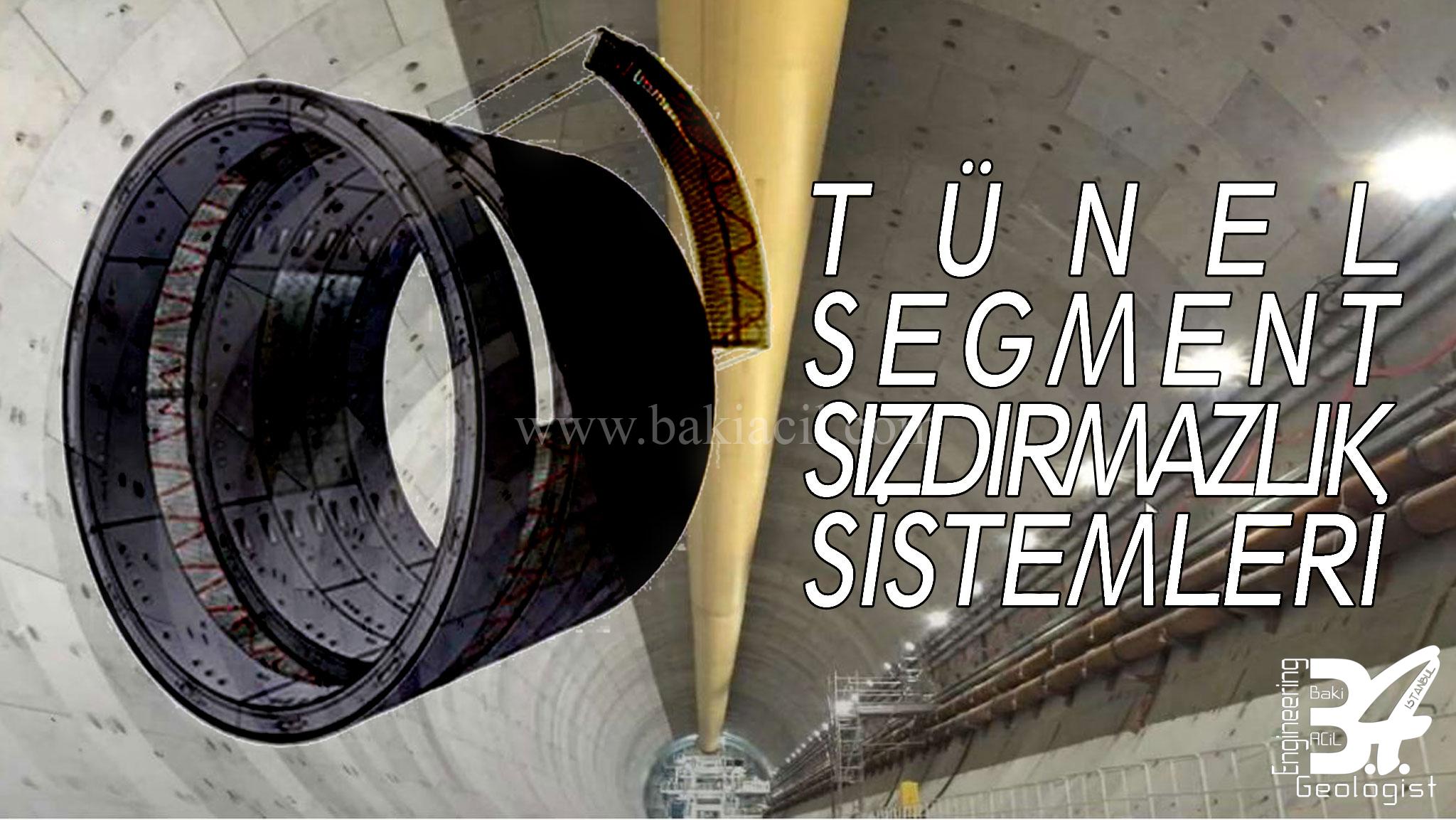
TUNNEL SEGMENT SEALING SYSTEMS
Infrastructure projects, like other world heritage sites, are seen as works that will be left for future generations. This document on the sealing frame system aims to provide guidance in selecting the most suitable gasket profiles both economically and technically, taking into account acceptance criteria specified in specifications. At the same time, recommendations are provided to prevent problems in advance in order to achieve high-capacity sealing. Based on experiences gained from domestic and international projects, the process from design to installation of the sealing frame is discussed.
Infrastructure projects, like other world heritage sites, are seen as works that will be left for future generations. This document on the sealing frame system aims to provide guidance in selecting the most suitable gasket profiles both economically and technically, taking into account acceptance criteria specified in specifications. At the same time, recommendations are provided to prevent problems in advance in order to achieve high-capacity sealing. Based on experiences gained from domestic and international projects, the process from design to installation of the sealing frame is discussed.
In the preparation of the document, all tests and analyses performed on the waterproofing system since 2012, site visits and problems encountered in the field along with the solutions produced, monitoring of the European Tunnel Committees and the experienced test laboratory on the subject in Europe, observations made during the STUVA visit, and the 17 years of experience gained in the rubber industry were taken into consideration. In waterproofing frames, it is possible to select both high-quality and cost-effective gasket profiles with knowledge and experience. Otherwise, gasket profiles that are cost-effective but do not achieve sufficient quality can cause project delays in the future and the waterproofing system to not work according to the desired criteria. As a result of the examination of experiences and foreign sources, it is aimed that the recommendations in determining the gasket profile selection and acceptance criteria will serve as a standard for all parties in the coming years. These recommendations will be expanded and constantly updated according to current technology over time.
1- SEGMENT TYPES
One of the most important considerations in segment design is ensuring longer segments with fewer T-joints. In tunnel segment linings, the T-joint areas are the most critical for waterproofing, so having longer sealing profiles and therefore fewer T-joints is of great importance for waterproofing. However, having fewer segments also directly affects project schedules, but it can lower costs by requiring fewer connection elements.
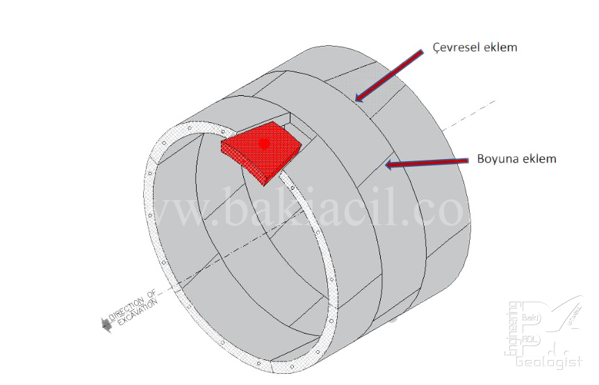
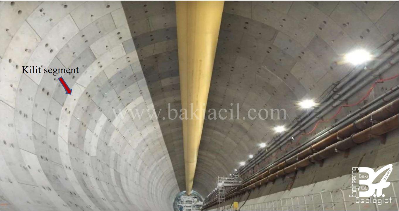
Tunnel projects commonly use rings consisting of 6 segments (5+1) as shown in Figure 1. Due to variables such as tunnel diameters, thrust forces, and segment weights, different ring configurations are required. Different lining types and geometries are also used within these types.
- Parallelogram – trapezoidal coating system
- Rectangular coating system
- Rectangular coating system
- Hexagonal coating system
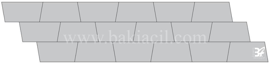
1.1 – Parallelogram – Trapezoid Coating System
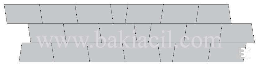
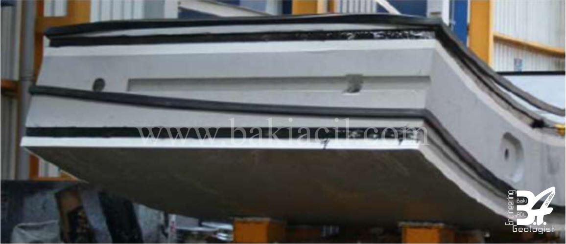
The most commonly used segment type in tunnel projects is the one that has good waterproof performance, can be assembled quickly, and has no early friction (see Image-2). The corners of the segments are formed at different angles, and the sealing gaskets may need to be compatible with the corner angles. Ring assembly is completed with a smaller key segment compared to other segments. The use of rapid connection systems such as Bi-Block is suitable.
1.2 – Rectangular Coating System
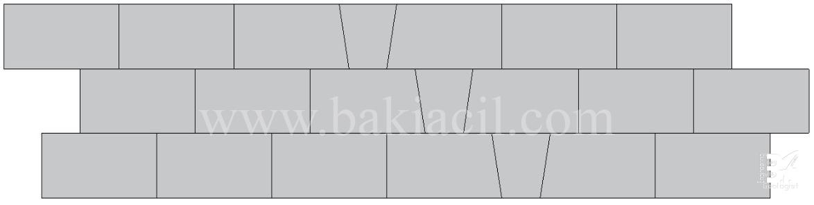
These segments consist of conical and rectangular shapes and are suitable for waterproofing, but friction can occur during the placement of rectangular segments, making their assembly more difficult compared to other systems. Therefore, assembly time is longer. Ring assembly is completed with a smaller key segment compared to other segments (Image-3, Image-4). Segment corners are formed from different angles, and sealing gaskets may need to be suitable for corner angles. They are more commonly used in very large tunnels.
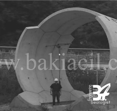
1.3 – Trapezoidal Coating System
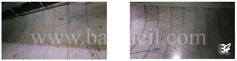
The segments inside the ring are divided into two halves: key and reverse key segments (Image-5). During assembly, the sealing gasket is not in contact for a long time, which prevents any damage to it. This also provides the advantage of shorter assembly time. Rings consist of an even number of segments. Segment corners are formed at different angles, and the sealing gaskets must be suitable for these angles.
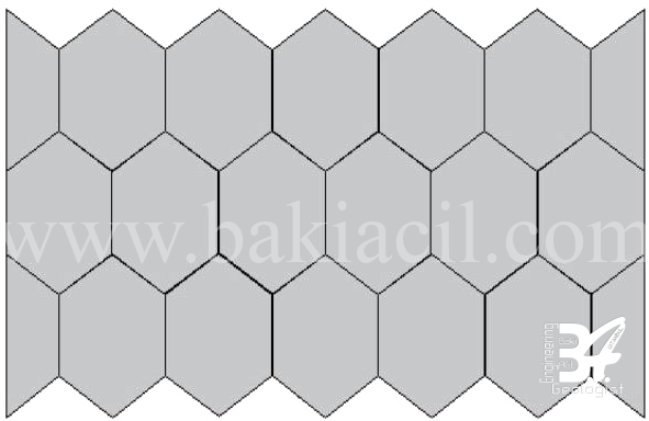
1.4 – Hexagonal Coating System
Another segment design that allows for very fast construction times is the hexagonal, or honeycomb, segment (Resim-6). Due to its geometry, it is difficult to compress the sealing gaskets, and the T-joints are very close to each other. Therefore, ensuring waterproofing can be challenging. This system is most suitable for impermeable soils where waterproofing precision is not critical and where the segment can self-support.
2 – SEGMENT GROOVES
It is also important that the segment grooves are within suitable tolerances as much as the back pressure of the segment sealing gasket. The tolerances determined by the German Tunnelling Committee (Deutscher Ausschuss für Unterirdisches Bauen e. V. German Tunnelling Committee ITA- AITES) for the compatibility of segment grooves with sealing gaskets are the most appropriate tolerances (Table-1). These tolerances may vary depending on the sealing gasket section specified in the project specifications. It is not recommended for the edge distance of the groove to be less than 30 mm (Figure-7). Groove edge distances closer to the edge can cause cracking and breaking near the groove.
Tolerances
Segment groove width ±0.2mm
Segment groove depth ±0.2mm
Position of segment groove axis ±1mm
Table-1
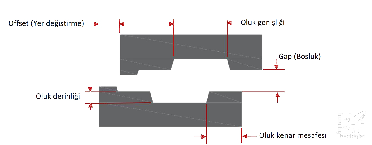
When the gap between the segment groove and gasket is zero, the gasket must contain its own net volume. Therefore, the gasket volume should be designed to be smaller than the groove volume, and the groove volume and gasket volume must be compared. Without load-displacement tests, which observe and interpret the comparisons, high forces will be required during assembly to achieve the desired compression, and potential problems will not be detected beforehand. High forces required for compression may lead to cracks, resulting in problems such as water seepage from the lower regions of the gasket and decreased concrete strength. These problems will require prolonged drainage work. Even if the design of the groove and gasket is appropriate, cracks may still occur near the groove. To avoid such damages, concrete quality and the experience of the TBM erecting operator are crucial. Assembly is a high-concentration task, and errors can cause delays and high costs. If cracks occur in the groove area or nearby, the gasket will not be able to perform its function and water seepage problems will arise. To ensure the gasket functions properly, the groove surface angles should be appropriate, and there should be no gaps or pores on the surface. Otherwise, leakage will occur from the lower regions of the gasket.
2.1 – Segment-Groove Position
The segment grooves can be located on the inner and outer surface. However, tunnels constructed for road or rail systems need to be resistant to groundwater. Therefore, it is necessary to position the grooves where the sealing gaskets will be placed on the outer surface. For water conveyance tunnels, it is recommended to position the segment grooves on the inner surface. If a double sealing gasket is used, it will be located on both the inner and outer surfaces (Figure-8). In all groove positions, the groove edge distance must be greater than 30 mm.
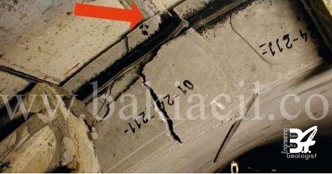
2.2 – Segment groove damages
Damages occurring inside or on the edges of the segment grooves can cause the circulation of groundwater beneath the sealing gasket, leading to the failure of the waterproofing system (Figure-9). Therefore, damages reaching the level specified in the specifications must be repaired. It is not recommended to repair very deep damages. After the repair process is completed and the suitability is checked, the sealing gasket is installed.
3 – CORNERS IN SEGMENTS
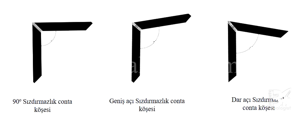
Segment corners are produced at different angles such as 80o - 90o - 100o (Image-10). However, problems with height or low level may occur at the corner edges due to their production at 90o for sealing gaskets. If the height or low level exceeds 5mm, sealing gaskets should be produced according to the angles on the segment. Sealing gaskets produced according to the angles on the segment provide perfect compatibility and enhance the performance of T-joints, which are the most risky in terms of sealing.
3.1 – Placement in Corners
Due to the standard method of placing the sealing gaskets on the segments through adhesive bonding, operators must ensure that the gasket is fully seated in the groove.
Sealing gaskets that are not completely seated in the groove can cause problems such as coming out of the groove during compression. Problems with incomplete seating in the groove, especially at corners, can adversely affect the sealing performance. During the installation of the first sealing gasket, the gasket manufacturer must also be present in the field. After a few sample tests, approval can be given once appropriate seating in the groove has been determined.
4 – SEALING PERFORMANCE OF SEGMENT CORNERS
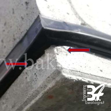
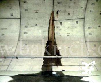
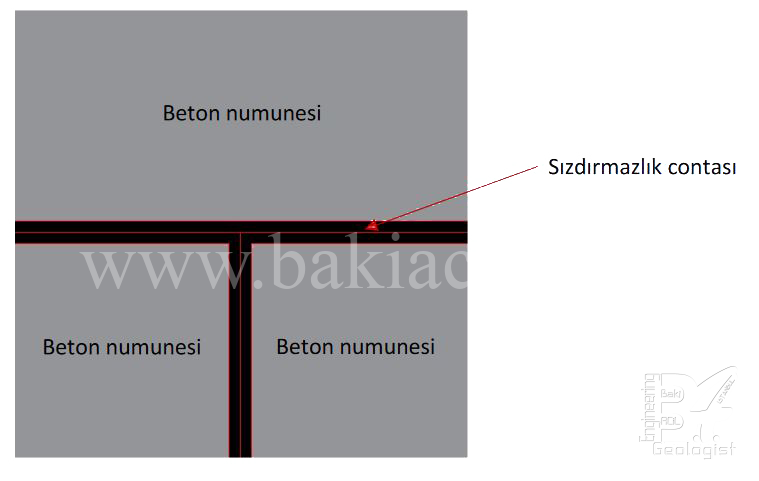
There are multiple segments within a ring, and rubber-based sealing gaskets are placed between these segments. T-joints, which are the corners of the segments, are the most critical areas in terms of water ingress for tunnels (Image-11). Therefore, as the number of segments within the ring and, consequently, the number of T-joints increases, the risk of water ingress in the longitudinal and circumferential joints of the tunnels also increases.
To eliminate this risk, Bi-block connection elements are used to ensure that the appropriate sealing gaskets and segments remain connected along the tunnel, thus preventing water from penetrating. The quality of the two materials that affect the sealing, proper geometry and tolerance in production, and optimal vulcanization values are among the most important components. Compliance with project specifications should be demonstrated by conducting appropriate testing in third-party testing laboratories.
4.1 – T-joint Leakage Test
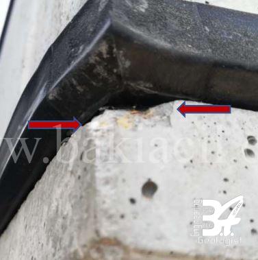
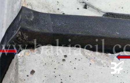
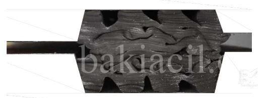
When longitudinal joints come together with segment corners, multiple sealing gaskets are brought together. It is not recommended for many sealing gaskets to come together at once for waterproofing (Image-12). Therefore, waterproofing tests should be conducted without considering such a connection system.
The majority of problems related to inadequate sealing in segments occur in the corners of sealing gaskets and sections approximately 100-200 mm away from the corners. Sealing tests are carried out for this area which is the most vulnerable to water infiltration. To avoid longitudinal joints, a minimum distance of 100 mm should be maintained along the circumferential joints, ensuring that sealing gaskets are kept away from the affected area. Test specimens are randomly selected from gaskets available at the construction site and brought to test dimensions in accordance with STUVA standards. The groove dimensions in the testing device must be identical to those specified in the project. Sealing tests are performed at offsets of 0-5-10-15-20 mm depending on the width of the sealing gasket.
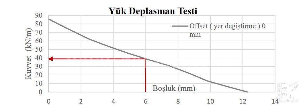
The offset and gap (clearance) values required by the project (e.g. Offset 10mm - Gap 6mm - 12 bar) are held under pressure for 20 hours. If no leakage is observed, the pressure is continued to be increased until leakage occurs to determine the maximum performance of the gasket. It is recommended to wait for 5 minutes for all pressure increments except for those required by the project's offset, gap, and bar values.
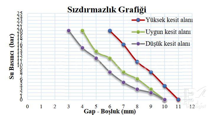
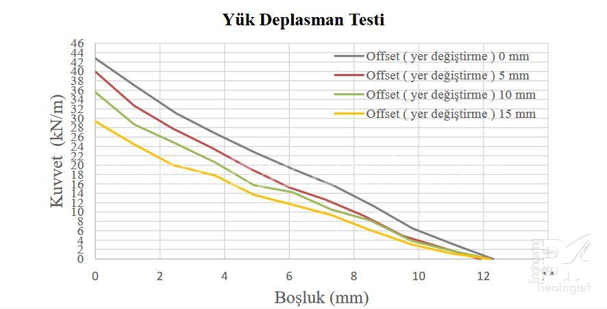
Sealing gaskets must have certain heights and contain gaps within their cross-sections to fill a certain amount of segment grooves. The filling amounts of segment grooves should be calculated considering the necessity of low compression force and high water pressure resistance. Graph 1 shows the sealing performance of the same type of segment sealing gaskets. As the groove filling volumes decrease, the sealing resistance also decreases. However, the negative effects of high groove filling volumes should also be taken into consideration.
The waterproofing between the segments is proportional to the contact of the segment gaskets with each other and the compression pressure. Therefore, the gasket profile and corners withstand groundwater pressure. As the offsets (displacements) increase, the surface contact area decreases and the resistance to waterproofing decreases accordingly (Figure-13). To stay on the safe side, segment assembly should be done with the minimum offset (displacement).
When offset tolerances are kept narrow, a narrower and smaller sealing gasket can be selected. However, this can slow down project progress and increase labor costs. On the other hand, if a wider sealing gasket is selected and the offset value is kept wide, it is possible to shorten project durations and reduce costs.
4.2 - T-joint Corner Load Test
The corner load test is not included in the current specifications for metro, road, and wastewater projects in our country. However, this test is just as important as the load displacement test performed on the sealing gasket profile. The specifications need to be updated, and this test should be included as an acceptance criterion. Two return forces on the corners are measured on randomly selected sealing gasket samples from the construction site. The groove dimensions in the testing device must be exactly the same as those specified in the project. The samples must be of the dimensions required by STUVA standards.
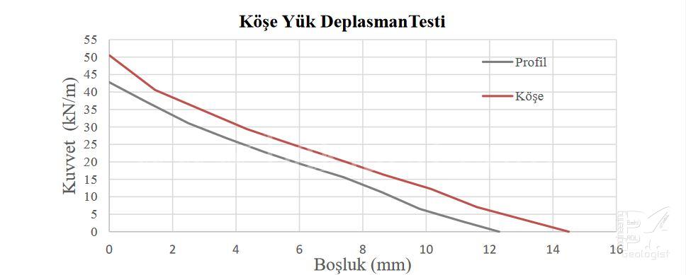
During the test, longitudinal joint specimens are compressed and hardened. Then, the return force that will be applied during the compression of the circumferential joint is determined. It is necessary to compare the results with the Gap 0 mm load displacement graph on the sealing gasket profile. The return forces above Gap 0 mm in both different tests should match or read close values to each other (Graph-2).
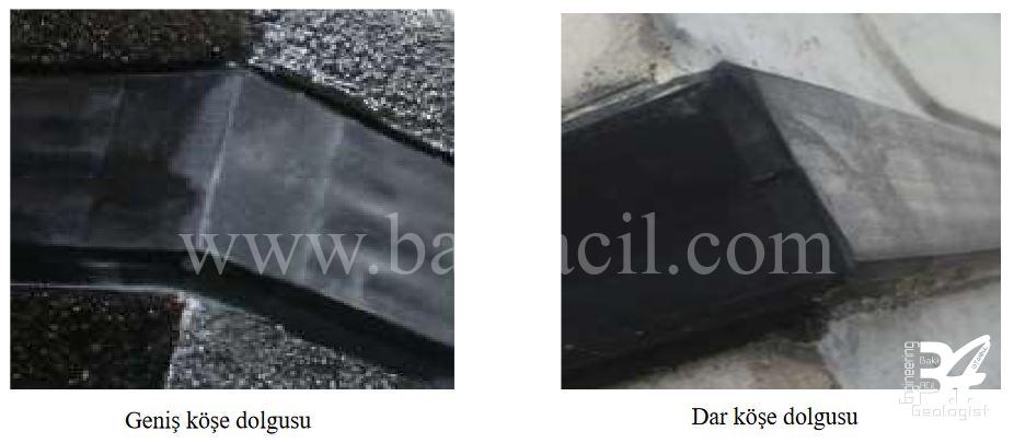
Near the segment grooves, crack and fracture problems can occur, especially in the corner areas. Therefore, the design of the sealing gasket corners should be based on the backforce that will occur. Sealing gasket corners can be used with reduced or filled-in corners according to the analyzed backforce. It should be noted that as the filling amount increases, the backforce in the corners will also increase. Since there are section gaps in the sealing gasket corners, it is recommended to keep the filling amount at a minimum level to stay on the safe side.
Recently, it has been observed in overseas projects that corner fillings are kept at a minimum level to stay on the safe side. In this way, more compatible results are obtained in gasket profile and corner load tests.
4.3 – T-joint Segment Spacing Behavior Test
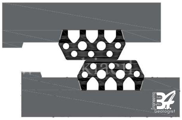
It is possible to test the high restoring forces that will occur in the sealing gasket on concrete (Figure-15). However, if the suitability of the restoring forces of the sealing gasket to be used in the project and its suitability in past projects have been proven by test results, this test may not be necessary. Tests should be carried out on concrete samples and preferably using the same or comparable concrete mix. The longitudinal joint is compressed as in the corner load test, and the restoring force that will come onto the circumferential joint during compression is determined. Thus, cracks or defects on the concrete surface are checked.
5 – SEALING GASKET SECTIONS
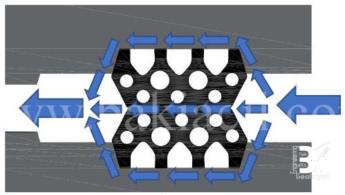
Segmental waterproofing seals fill the segment grooves by compressing against each other and show an increase in stiffness (Figure-16). For a healthy compression to occur, the geometry of the seal must allow it. It is important that the groove dimensions are analyzed very carefully by the seal manufacturer.
5.1 – Return Forces at the Sealing Gasket
The load displacement test is carried out on test specimens randomly selected from the seals available on the construction site, and the dimensions of the test specimens are adjusted to the STUVA standards. The groove dimensions in the test apparatus must be identical to the groove dimensions specified in the project. Load displacement tests are conducted at offsets of 0-5-10-15-20 mm depending on the width of the seal (Graph-3). The force obtained after holding the specimen under load for 5 minutes at the minimum groove base distance in accordance with STUVA acceptance criteria is considered the seal's reverse force.
Due to inappropriate stiffness, geometry, measurement errors, poor mixture use, and faulty design in sealing gaskets, their volume may exceed the segment groove capacity, causing cracking and fracturing problems in segment concrete. Two types of the same sealing gasket may exhibit different behaviors (Graphs 4-5). Therefore, the knowledge and experience of the manufacturer about this subject are crucial.
The greatest return force occurs at offset 0 mm. As the offset amount increases, the surface contact area in segment sealing gaskets decreases and accordingly the return force decreases. The back force occurring at offset 0 mm should be taken into account and stay on the safe side. Load displacement test charts should be well evaluated within the scope of the project. The values that will occur in this graph are important in terms of sealing, as well as the values that may occur in the segments.
Cracks and also affect the performance of Bi-block fasteners. In the following sections, the bond between sealing gaskets and Bi-block is mentioned.
5.2 – Loosening of Sealing Gaskets Over Time
Projects such as subways, road tunnels, and wastewater systems serve for many years and are left as a legacy for the future. Therefore, the waterproofing performance of such structures must also maintain its continuity for the same period. Over time, sealing gaskets loosen, and their waterproof properties decrease in the same proportion. One of the reasons for determining the safety factor expected against water pressure in projects is due to this issue. Loosening progresses faster in the first few months compared to later periods. Since the operating temperature of sealing gaskets will not reach 70 C, it is not appropriate to estimate the loosening after 100 years based on this temperature. In Graph-6, approximately 38% loosening is observed after 90 days. The test should be conducted at 20-30 C instead of the accelerated aging temperature of 70 C,
and the data obtained during the test period should be extrapolated to show the estimated loosening within 100-120 years (Graph-7).
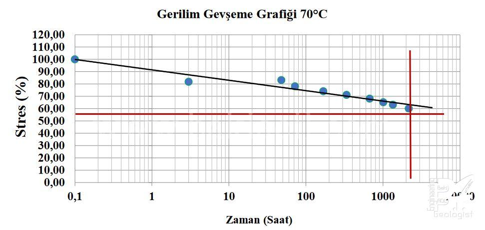
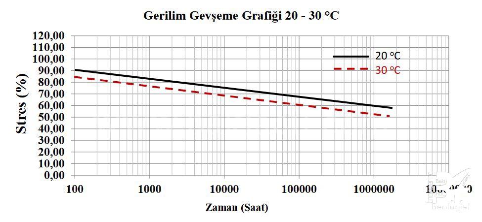
In the sealing gaskets used in segment joints, the pressure within the groove decreases as a result of the looseness that occurs over time. Therefore, the force relaxation calculated for 100 years should not exceed 45%. The allowable relaxation in the specifications in our country is a maximum of 50%. Incorrect statements such as "the residual stress at the end of 100 years will not exceed 50%" and "the remaining pressure after 100 years should not exceed 50%" have been used in the current specifications in our country. The residual stress (stress remaining in the material) on the sealing gasket and the remaining pressure on the gasket should not exceed 50%. From a technical perspective, there should be a minimum level of stress relaxation for the sealing gaskets to perform their function.
5.3 – Other Tests
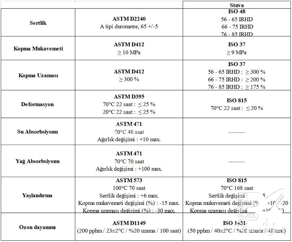
There are some differences between the recommended tests and acceptance criteria in Stuva standards and those used in the specifications in Turkey (Table-2).
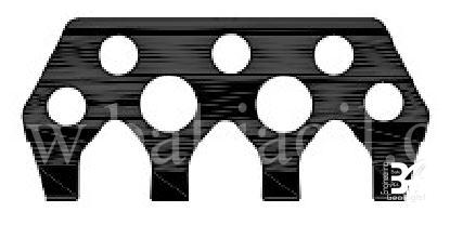
6 – BI–BLOCK FITTINGS
Bi-Blocks are advantageous in terms of fast installation and less manpower. In large-diameter tunnels, if the cutting force is insufficient, the connection elements are assembled with a bolting system. Although bolts have high tensile and yield strength, their installation times are prolonged.
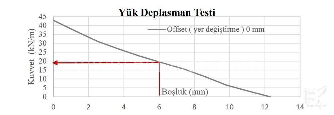
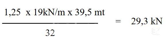
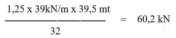
During segment installation, the back-force on the sealing gasket creates a tensile force in Bi-Block connection elements. This force only occurs when the TBM thrust cylinders are retracted, i.e., during the next ring assembly. Bi-Block connection elements must withstand the back-force from the sealing gasket. Otherwise, the desired compression cannot be achieved, and the sealing properties specified in the project may be lost. They must also withstand the shear forces that will occur. Different back-forces may occur on the same two types of sealing gaskets due to reasons such as measurement, mix quality, unsuitable geometry, and unsuitable groove filling volumes. The back-forces on the sealing gasket and the tensile forces in the Bi-Block pull test should be compared. If corner load tests have not been performed or analyzed, a safety factor of 1.25 is recommended when considering the back-force values in the load displacement graph. The maximum gap between segments should not exceed 6 mm.
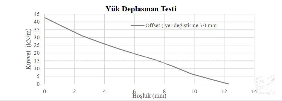
For example, in a project where the sealing gasket axis is Ø12.6 m and a total of 32 Bi-Blocks are used along the ring, the reverse force on the sealing gasket should be less than the tensile force on the Bi-Blocks. According to the sealing gasket load test in the graph, the tensile force on one Bi-Block at an offset of 0 mm and a gap of 6 mm is 29.3 kN (Graph-8).
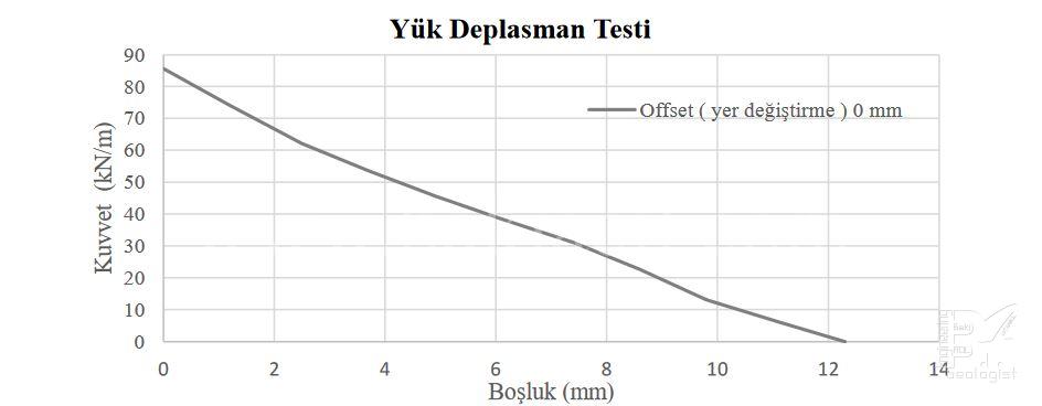
According to the leakage sealing test on the graph, the tensile force that will be applied to one Bi-Block at an offset of 0 mm and a gap of 6 mm is 60.2 kN (Graph-9).
In the Bi-Block pull test, a displacement of 10 mm was recorded, and a force of 54.1 kN was obtained at a gap of 6 mm (Table-3).
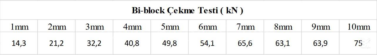
When we compare the seal load displacement tests with the Bi-Block pull tests, it can be seen that the 29.3 kN pull force obtained on one Bi-Block in graph-8 will cause an approximately 3 mm opening between the segments. On the other hand, in graph-9, the obtained pull force on one Bi-Block is 60.2 kN, and this will cause an approximately 6.5 mm opening between the segments. If the seal does not have suitable return forces and transmits more force than expected to the Bi-Blocks, it will cause a greater opening of the gap distance, leading to a decrease in the seal performance. In this case, the obtained return forces in graph-9 will cause an excessive opening
between the segments and the expected sealing performance will decrease.
Different pull-back forces can be detected on two identical types of sealing gaskets during load displacement tests, as well as different pull forces on two identical Bi-Blocks. It is necessary to prove and compare these different forces due to reasons such as the quality of the mixture used and the design. In addition, due to the stresses and bending forces that will occur in the segments, a shear test must be performed on the Bi-Block connecting elements.
7 – SEALING GASKET TYPES
There are many tunnel segment sealing gasket manufacturers and gasket types around the world. The common goal of all designs should be to seal within the appropriate return forces. Inter-segment gaps, offset (displacement) and underground water pressures that will occur within the scope of the projects are very important for sealing gasket design. As seen in all the tests performed, the appropriate return forces depend on the geometry of the gasket as well as the quality of the mixture used. Therefore, sealing gasket design is based on knowledge and experience.
7.1 – Standard Segment Sealing Gaskets
It is the most commonly used sealing gasket type today (Picture-18). They are most commonly produced in widths of 20, 26, 33, 36 and 44 mm according to underground water pressures, tunnel diameters and offset amounts. The assembly begins by placing the corners into the segment groove with the bonding method. It is then placed towards the corners starting from the middle with the help of a plastic hammer. It is necessary to make sure that the sealing gasket is completely inserted into the groove.
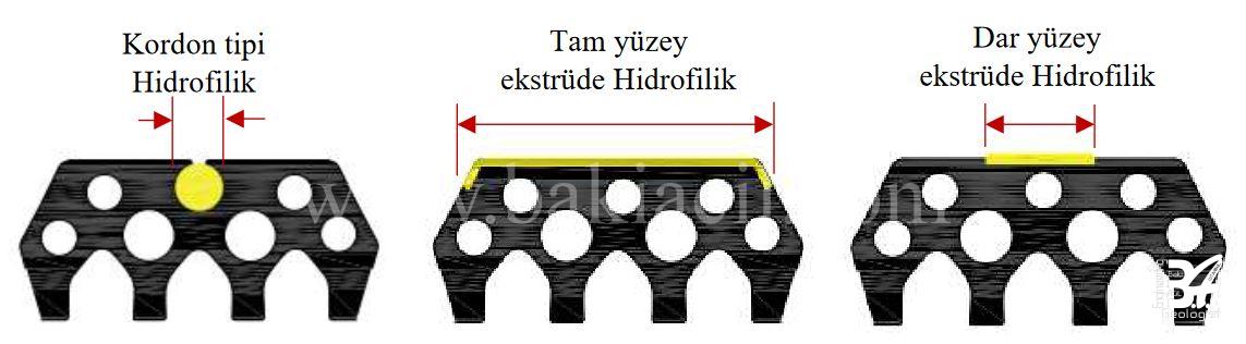
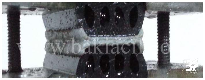
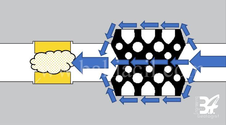
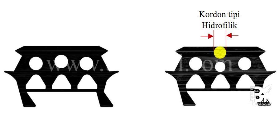
A hydrophilic surface can be added to the standard sealing gaskets for security purposes (Picture-19). Hydrophilic sealing gaskets provide additional security and start to swell in contact with water, closing the leaking area (Picture-20). In cord type hydrophilic sealing gaskets, the hydrophilic surface is not extruded and is placed after the gasket is installed in the groove. It should be protected from moisture and water during transportation and storage. These conditions must be met until you enter the tunnel.
Hydrophilic tape surfaces can also be used on the side surfaces of sealing gaskets. It is positioned on the inner surface, except for the sealing gasket. It is used as an additional measure on the inner surface against the risk of water leakage in the sealing gasket (Picture-21).
7.2 – Anchored Sealing Gaskets
Anchored sealing gaskets are placed in the segment mold from the concrete casting stage without placing the reinforcements (Picture-23). The anchors in the lower part remain in the eton and additional processes such as bonding are not needed. Operators must be experienced and careful when placing the gasket in the segment mold. Care should be taken to ensure that the anchor feet are in the upward direction during placement. In addition, there are no problems such as coming out of the groove during the transportation or assembly of the segments. The geometry of the sealing gasket is very important to avoid concrete leaks. Therefore, the segment mold and sealing gasket design should be carried out jointly. T-joint placement performances are at a high level in all segments. Hydrophilic surface can be integrated on it (Picture-22).
Source
- STUVA – Forschung + Praxis 54 Recommendation for Gasket Frames in
- Segmental Tunnel Linings
- Alman Tünel Komitesi (Deutscher Ausschuss für Unterirdisches Bauen e. V.
- German Tunnelling Committee ITA-AITES)
- ITA – AITES Guidelines for the Design of Segmental Tunnel Linings
İÇİNDEKİLER
1- SEGMENT TİPLERİ…………………………………………………………….
1.1 -Paralelkenar – Yamuk Kaplama Sistemi………………………………
1.2 -Dörtgen Kaplama Sistemi…………………………………………………..
1.3 -Trapez Kaplama Sistemi…………………………………………………….
1.4 -Altıgen Kaplama Sistemi…………………………………………………….
2- SEGMENT OLUKLARI………………………………………………………….
2.1 -Segment-Oluk Konumu………………………………………………………
2.2 -Segment oluk hasarları………………………………………………………
3 -SEGMENTLERDE KÖŞELER……………………………………………….
3.1 -Köşelerde Yerleşim……………………………………………………………
4- SEGMENT KÖŞELERİNİN SIZDIRMAZLIK PERFORMANSI…….
4.1 -T-derz Sızdırmazlık Testi……………………………………………………
4.2 -T-derz Köşe Yük Testi……………………………………………………….
4.3 -T-derz Segment Kavlama Davranışı Testi…………………………….
5- SIZDIRMAZLIK CONTASI KESİTLERİ……………………………………
5.1 -Sızdırmazlık Contasında Geri Dönme Kuvvetleri……………………
5.2 -Sızdırmazlık Contalarının Zaman İçerisinde Gevşemesi…………
5.3 -Diğer Testler……………………………………………………………………..
6- Bİ–BLOCK BAĞLANTI ELEMANLARI…………………………………….
7- SIZDIRMAZLIK CONTASI TİPLERİ………………………………………..
7.1 -Standart Segment Sızdırmazlık Contaları……………………………..
7.2 -Ankrajlı Sızdırmazlık Contaları…………………………………………….,
I would like to thank Serhat ÖZALP, the authorof this valuable article, for allowing me to share this article on my site.